Il laboratorio XACT
The X-ray beamline
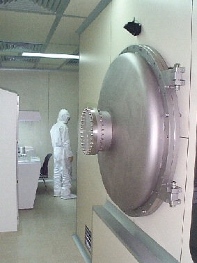
The 35 meters long X-ray beamline consists of an X-ray source, a monochromator chamber 0.8 meter diameter and 1 meter height, 16 tubes with lengths of 1, 2, or 2.5 meters, a big chamber 3.5 meters long and 2 meters in diameter to test grazing incidence telescopes, and a detector test chamber 1 meter long and 1 meter in diameter (Fig. 1).
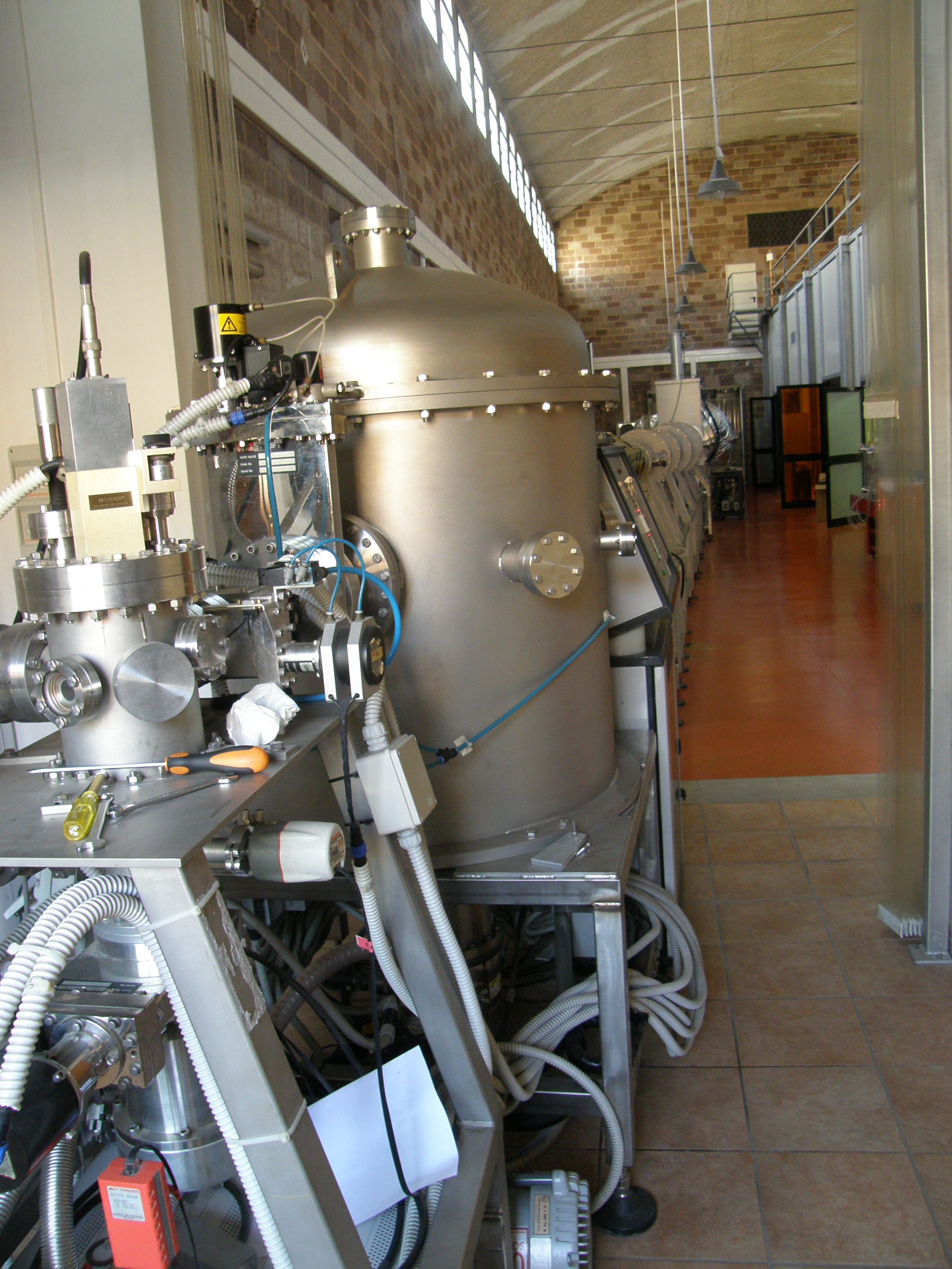
Fig. 1 – Picture of the X-ray beamline of the XACT facility. The X-ray source and the X-ray monochromator chamber are in foreground.
The diameter of the tubes increases from the source end (150 mm) to the telescope test chamber to allow a full area illumination with a diameter of 800 mm, minimizing the volume and the internal surface of the pipe. All tubes are provided with large size side ports (CF standard from 100 to 250 mm diameters, ISO standard from 300 to 500 mm diameters) to access the experiments, a number of small size ports (CF standard with diameters ranging from 40 to 200 mm) for feed-throughs, monitoring, vacuum gauges, and mechanical support to the experiments, and ports to attach the vacuum pumps (ISO standard with diameters ranging from 100 to 250 mm). The monochromator chamber, with a diameter of 800 mm, is located just after the X-ray source (Fig. 2A). The telescope test chamber is equipped with a 1400 mm diameter opening door (Fig. 2B). The temperature of the chamber can be controlled to ensure thermal stability at the test temperature. One of the beam-line tubes is a Tee with 630 mm diameter and side door of the same diameter located at half the length of the beam-line specifically designed to test prototype optics with cylindrical geometry. The detector test chamber located at one end of the beam-line has a 1 meter diameter door opening inside a class 1000 clean-room (Fig. 2C). The vacuum chamber has been manufactured by CINEL, Vigonza (Pd), Italy (tubes with diameters under 630 mm, and detector test chamber) and by SIMIC, Camerana (CN), Italy (Tee with diameter of 630 mm, tubes with diameters of 800 mm, monochromator chamber, telescope test chamber). The vacuum pumping system is entirely based on magnetic levitation turbo-molecular pumps, and on oil-free rotary pre-vacuum and back-up pumps. A minimum pressure of 5×10⁻⁸ mbar can be achieved, while normal operation is in the 10-7 mbar scale. The vacuum pumping system has been provided by BOC-Edwards.
The Ultraviolet beamline
An UV/visible ebamline is attached to a side port of the detector test chamber (Fig. 2D). The beamline is equiped with a Rowland circle-mount grazing-incidence reflection-grating monochromator, covering the 10-3000 Å range, that can mount different sources (gas discharge and electron impact).
-
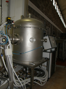
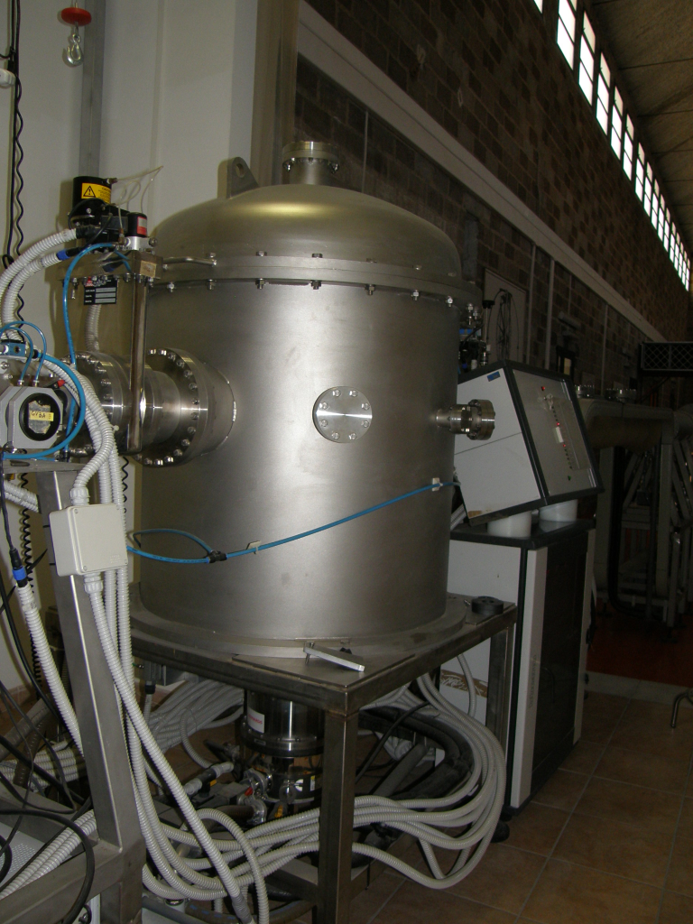
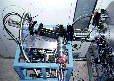
- Fig. 2A – Chamber hosting the double diffraction X-ray monochromator
-

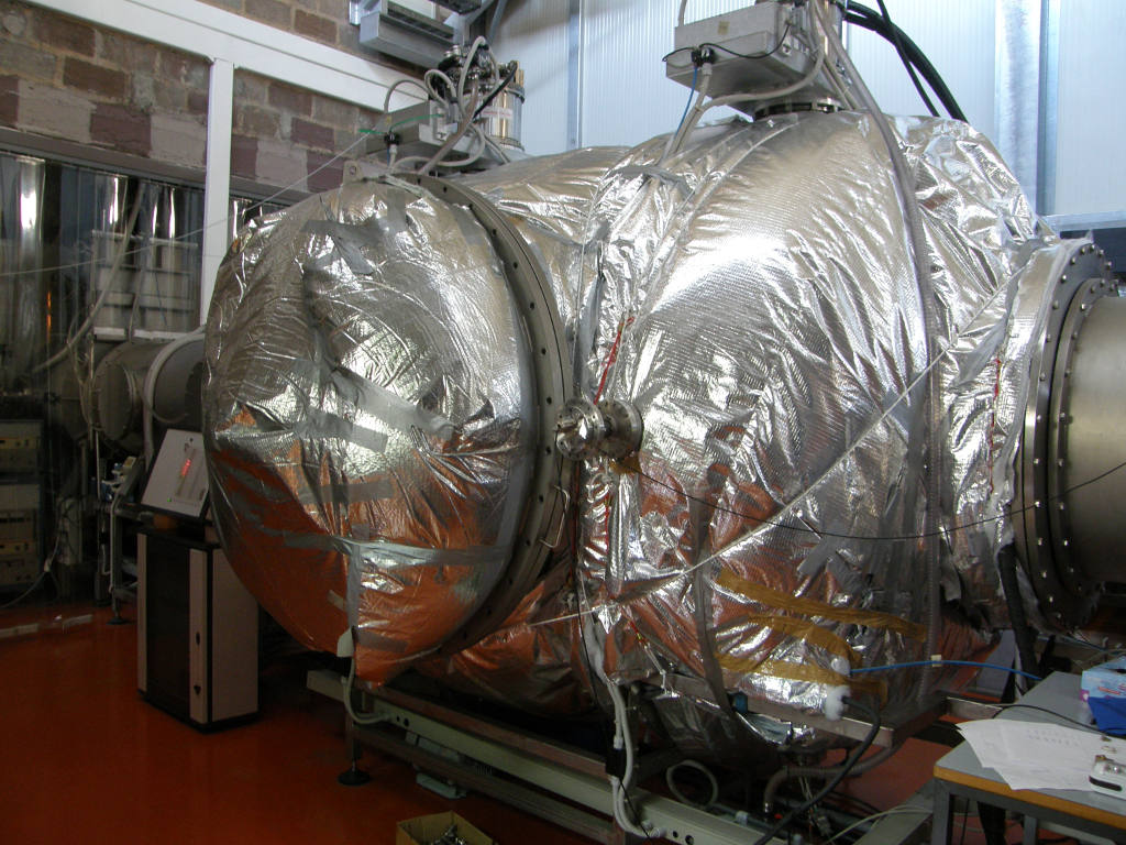
- Fig. 2B – Telescope test chamber equipped with a side door of 1400 mm in diameter
-

- Fig. 2C – Detector test chamber opening inside a class 1000 clean-room
-

- Fig. 2D – Ultraviolet beamline attached to a side port of the detector test chamber.
Sources, Monochromators, and Detectors
Different sources, monochromators and detectors allow to perform measurements ranging from UV to soft X-rays.
X-ray monochromators
- A soft X-ray monochromator (0.1-2.0 keV) consisting of an adjustable (5-2000 μm) entrance slit (slit 1) to focus the beam, an AXAF type LETG transmission grating facet (1000 lines/mm), and an adjustable exit slit (slit 2) to select the energy of interest. The entrance slit and grating facet are mounted on a magnetically coupled linear translator with 30 cm linear travel at about 7 meters from the detector test chamber. The monochromator provides a FWHM pass band of nearly 1 Å. Its efficiency is of few percent (with respect to direct beam from the source) with an available spot size at the test chamber of nearly 1 x 20 mm2.
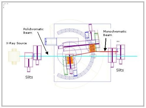
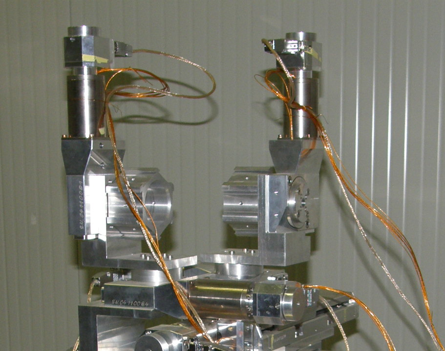
- A double diffraction monochromator working in the 0.1-30 keV range. The exit beam is fixed (the position does not depend on the selected energy) and parallel to the incident beam (Figure 4 left panel). The concept is the same proposed by Mills and King (1983) (Fig. 3) and already implemented at the Physics department of the Università di Ferrara. The need for such wide energy range has dictated the employement of many interchangeable dispersive elements. In the implemented configuration, up to 7 pairs of dispersive elements can be mounted on a caroussel and selected under vacuum (Fig. 3 right panel). The device is presently operating in the 1-30 keV range employing RbAP, TlAP, quartz, pyrolitic graphite, silicon and germanium flat crystals. Graphite, silicon and germanium have been machined to have a mosaic of mono-crystals with orientation angles spread in the range from few arcsec to few degrees to obtain different width of the energy passband, flux intensity, and beam divergence. Preliminary studies have suggested the use of multilayers as dispersive elements at low energies (E < 2 keV), where reflectivity of organic cristals is rather low. Depending on energy and dispersing element, a quite large beam (~ 60×30 cm2) can be obtained at the telescope test chamber.
-

- Schematic drawing of the double diffraction X-ray monochromator
-

- The carousels that can mount up to seven dispersing elements
UV monochromator
A 1 meter Rowland Circle mount grazing incidence monochromator manufactured by McPherson Inc. (Chelmsford, MA, USA), model 248/310G. It consists of an adjustable slit (5-3000 μm) that travels with the light source along the Rowland circle, a concave grating, and an exit adjustable slit (5-3000 m). The two available gratings, namely 133 grooves/mm and 600 grooves/mm, allow a spectral coverage of the wavelength range 10-3100 Å. The monochromator provides a nominal spectral resolution of nearly 2 Å with the 133 grooves/mm grating.
X-Ray Sources
- An electron-impact multi-anode micro-focus Manson model 5 manufactured by J.E. Manson CO. Inc. (Concord, MA, USA) located at the end of the main X-ray vacuum beamline. This source is equipped with six different anodes and four different filters that can be selected without breaking the vacuum. The power supply system has been modified to allow X-rays to be emitted up to 20 keV. The X-ray source is very efficient. It can be operated with only 5 Watts, does not require any anode cooling system, and can produce a flux up to 105 photons/(cm2 s) at about 20 meters distance. The quite strong X-ray flux permits to run measurements with short exposures, and allows the use of a monochromator;
- An electron impact single anode Manson model 2 manufactured by Austin Instruments Inc. (Reading, MA, USA ) that can be also attached to the grazing incidence monochromator of the UV/Visible beam-line.
- An electron impact water cooled single anode built in house soft X-ray source able to produce a flux up to 107 photons/(cm2 s) at about 20 meters distance
UV Sources
- An hollow cathode gas discharge source manufactured by Mc.Pherson, Inc. sufficiently light and compact to be mounted on the movable slit assembly of the grazing incidence monochromator. The source produces a number of intense emission lines in the 200 – 2000 Å range, by means of an electrically excited gas discharge within a hollow cathode;
- A Gas Discharge Penning Source manufactured by Berkeley Photonics (Berkeley, CA, USA) that provides bright lines in the 50-350 Å range;
- A Pen-ray mercury discharge lamp manufactured by UVP (San Gabriel, CA, USA) that provides a useful calibration line at 2537 Å.
X-Ray detectorsµ
- Two commercial Gas Flow Proportional Counters manufactured by LND (Oceanside, NY, USA) and one manufactured by J.E. Manson CO., Inc. with nearly 34 % energy resolution at 1.5 keV;
- A micro-channel plate based detector with resistive anode encoder and front plate coated with KBr manufactured by Quantar Technology Inc. (Santa Cruz, CA, USA) with 40 mm active diameter, and 100 µm spatial resolution.
- A Si PIN Solid State Detector model XR-100CR manufactured by Amptex Inc. (Bedford, MA, USA), with 13 mm2 sensitive area and 12.5 µm thick Be entrance filter, sensitive in the energy range 1.5 – 30 keV with a typical energy resolution of 2.5 % at 6 keV.
UV detectors
- The MCP previously described which has an efficiency of few percents up to about 1200 Å.
- A Photomultiplier tube with Cs2Te photocathode and a MgF2 window manufactured by EMR Photoelectric (Princeton, NY, USA) that provides efficient photon counting in the 1150-3550 Å range.
- A Windowless Silicon Photodiode manufactured by IRD Inc. (Torrance, CA, USA), model UVG-100, calibrated at the National Institute of Standards and Technology (NIST, Gaithersburg, MD, USA), with a high sensitivity in the 50-2500 Å range and an active area of 1 x 1 mm2.
- A Silicon Photodiode manufactured by UDT Sensors (Hawthorne, CA, USA) model UV100, calibrated at NIST, with a high sensitivity in the 2000-5000 Å range and an active area of 1 x 1 mm2.
- A Silicon Photodiode manufactured by Hamamatsu Corporation (Bridgewater, NJ, USA) model S2281, calibrated at NIST, with a high sensitivity in the 4000-10000 Å range and an active area of 1 x 1 mm2.
|
Wavelength [Å] |
Source | Monochromator | Detector |
| 1-100 |
|
|
|
| 50-350 |
|
|
|
| 300-1200 |
|
|
|
| 1100-3000 |
|
|
|
Vacuum Compatible Micro-Positioning Systems
Approximately 20 stages are available in the beam-line including nine axis to operate the double diffraction monocromator (Fig), 2 rotary stages dedicated to an alt-azimuth mount to test grazing incidence X-ray optics, two rotary stages and three linear stages employed in a soft X-ray grazing incidence reflectometer, a number of linear stages to move slits, filters, pinholes, and detectors inside the detector test chamber, and a long travel (50 cm) linear stage used to scan the image quality of focusing optics along the focal axis. Most of the available stages are manufactured by MICOS GMBH (Eschbach, Germany) and by NEAT (Salem, NH, US). All stages can be remotely controlled via serial or TCP/IP protocols.
Remote Control and Operation of the Facility
Figure 4 shows a schematic drawing of the architecture of the XACT facility operation and control system. Seven modules have been identified to carry out all the control and measurement activities. All computers running the individual modules are connected to the LAN of the XACT facility and share relevant system parameters. The software applications are developed under National Instruments Labview with moderate use of external routines developed in other programming languages. The computers running the operation and control software modules interact via TCP/IP, Serial, and GPIB protocols directly with the instrumentation controllers (e.g. turbo pumps, vacuum gauges, stepper motors) and via a number of I/O modules National Instruments FieldPoints, distributed in the facility, to read the system status and operate it (e.g. open/close valves, turn on/off pumps, read valve status etc.). A master software module, which will be continuously developed with time, will run all the measurement procedures and will interact with most of the other modules.
Cryogenic Laboratory
An Adiabatic Demagnetization Refrigerator (ADR) was designed and built at the XACT facility.16. The ADR is based on a standard LHe dewar modified to accommodate the ADR stage (superconducting magnet and paramagnetic salt pill) inside the LHe vessel. .
We have developed in house the expertise and techniques to grow a quite large size crystal of Ferric Ammonium Alum and to build the salt pill housing (SPH). The fully constructed SPH is suspended on Kevlar wires inside the superconducting magnet. The magnet, in thermal contact with the pumped LHe bath, is surrounded by a thick shield of high magnetic permeability material (Hyperco 50A) to reduce the magnetic field at the location of the detectors under test. The measured minimum temperature is presently 45 mK and the measured heat load onto the salt pill is 0.1 μW, both numbers in very good agreement with theoretical expectations. A PID control algorithm allows us to maintain the salt pill temperature stable to within 5 μK at 60 mK.
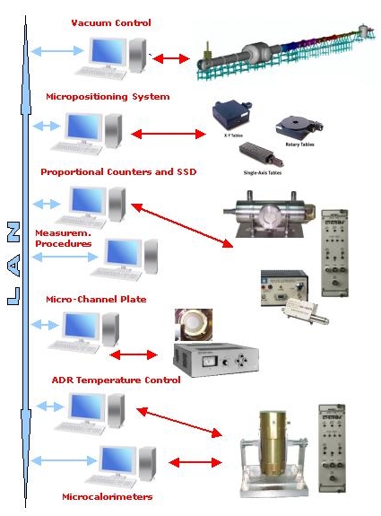
Schematic drawing of the architecture implemented to control and operate the XACT facility and run test and calibration measurements.
Microtechnology laboratory
Activities ranging from x-ray detectors development to fabrication of carbon-nanotubes cold-cathode x-ray sources are supported by the following thin film technology equipment:
- E-beam evaporator: three crucibles high-vacuum pyhsical vapour deposition system for thin film deposition.
- MW ECR PE-CVD (MicroWave Electron Cyclotron Resonance Plasma-Enanched Chemical Vapour Deposition system) for thin film and nano-structured surfaces synthesis.
- Spin-coater.
- Lapping/polishing machine.
600 °C ventilated oven, with sealed stainless steel chamber for non athmospheric treatments. - Vertical and horizontal flux clean benches.
- UV exposure unit.
- Electroplating equipment.
Tools and accessories
- A 15 m2 certified class 1000 clean-room. The Clean-room is provided with a class 100 laminar flow bench, a dry Nitrogen cabinet for sample storage and a pass-through with interlocked doors;
- A 30 m2 class 10000 clean-room.
- Machine shop equipped with CNC lathes and milling machines;
- Optical microscope with digital camera and frame grabber;
- Chemical fume hood;
- Equipment to stretch polypropilene films down to about 1 μm thickness for proportional counter windows;
- Equipment to wind fine meshes for proportional counter windows;
- Equipment to grow FAA paramagnetic crystals for Adiabatic Demagnetization Refrigerators.